Applying QRM to Air Change Reduction

The following is an example of an evaluation of room air change rates for potential reduction using QRM, providing more detail on engineering considerations.
Basic Engineering Considerations
When evaluating room air change rates, always remember that the airflow to a room must be adequate to:
- Maintain the room temperature and humidity at values sufficient to meet any product/process and occupant comfort requirements
- Maintain room airborne particle concentration levels below established limits for rooms with formal cleanroom classifications (e.g., Grade C, ISO 8)
- Dilute airborne particle concentrations below limits for occupant product exposure
- Dilute any vapors to concentrations below either occupant exposure or flammable vapor limits
- Provide make-up air to offset process-related room exhaust flows (e.g., dust collection exhaust)
- Maintain differential pressures between rooms/spaces to help limit the movement of airborne contaminants between spaces
High Air Change Rate And Control Of Particle Movement
High room air change rates, when coupled with directional flow, can aid in controlling airborne particle movement. A Grade A unidirectional airflow area is an example, as is a down flow (e.g., weigh) booth. The air change rate in most pharmaceutical manufacturing rooms, however, is not nearly as high as in a Grade A area or a down flow booth and, at best, has a minor effect on particle movement. It is also worthwhile remembering that these areas that benefit from such high air change rates are proportionally smaller than the lower risk support areas within the facility. The benefits that can be achieved through reductions in these higher risk areas are also proportionally lower when compared with the execution level of difficulty.
“Guidance values for air change rate are frequently misinterpreted as requirements”
Reduced Air Change Rates
The air change rate can either be reduced at all times, or only during off hours. Sometimes It might be possible to reduce the air change rate during occupied/production times combined with a further reduction during off hours.
Reducing the room’s air change rate at all times generally involves a rebalancing of the flows to the new lower rates and adjustments to assure proper room pressure relationships, etc. This rebalancing can be done on HVAC systems that do as well as those that do not incorporate room level airflow control devices (i.e., automatic or remotely adjustable volume control/regulating devices such as variable volume boxes, mechanical constant volume regulators, or automatic room pressure controls at individual rooms). Reducing airflows only during off hours can be more complicated than reducing the normal air change rate because of the dynamic nature of this approach (two operating modes). Issues such as how long the room takes to achieve the required normal operation parameters (e.g., temperature, humidity, air change rate, pressurization) when switching from reduced flow/off hours operation to normal operation must be addressed. Reducing room air changes during off hours is most likely to be successful when the HVAC system incorporates room level airflow controls because these control devices can usually be set up to maintain the proper room pressure relationships at both the normal and reduced flow rates. Control of the capacities of the main system fans to maintain a stable main duct pressure is also desirable so that the room level controls will not be over pressured and also to save fan energy.
Particle Count And Room Air Changes
There is a definite relationship between a room’s air change rate and its airborne particle count whenever the particles are generated within the room. The particle count of air supplied to the room by the HVAC system is, however, a function of filtration, not room air changes.
The relationship between air change rates and room airborne particle counts can be approximated by the following relationship: Cave = Csa + PGR/ACH
Where:
Cave = Average room airborne particulate count
Csa = Particulate count of supply air
PGR = Particle generation rate due to room activities
ACH = Air changes per hour
When working with high efficiency filters such as H14 HEPA, or U15 ULPA, the supply air particulate count is sufficiently low as to be considered negligible. Based on this, the main driver for air change rates is the rate of particle generation within the space. Areas of low activity will typically have considerably lower particle generation rates, and other controls such as gowning and cleaning will further impact particle generation.
Technical and regulatory considerations for rooms with a formal cleanroom classification
Classified rooms (e.g., EU Grade C, ISO 7) have defined limits for airborne particle concentrations and usually support the manufacture of sterile products or certain biological products. The room air change rate must be sufficient to dilute the room-generated airborne particles to meet the defined limits. Rooms designed with air change rates that were based on industry practice (i.e., “rules of thumb”) have often been found to operate at a cleaner grade/class than needed. Experience with installations that have reduced air changes has shown that many such rooms can be operated at reduced air change rates and still stay comfortably within airborne particle count limits.
The EU GMP Annex 1 (sterile manufacturing) 3 no longer mentions air changes. The US FDA guideline for sterile drug products produced by aseptic processing notes that “for Class 100,000 (ISO 8) supporting rooms, airflow sufficient to achieve at least 20 air changes per hour is typically acceptable.” 2 Many rooms of lower grade/class should be able to operate below the 20 air change “limit” and still meet airborne particle count limits.
Facilities serving markets outside the US must often demonstrate not only that they meet particle count limits in the “operational” mode, but also in the “at-rest” mode (no people present), and that the particle count will achieve the at-rest level within a reasonable amount of time (e.g., 15–20 minutes) after production operations cease (“recovery” time).
A short recovery time is an indication of thorough (effective) ventilation of the room. It is the combination of the room air change rate and the type and placement of air introduction and air extract devices that determine how effective the HVAC is at ventilating a room for the removal of airborne contaminants. Good design of room air introduction and extract devices and their locations increases the ventilation effectiveness and generally allows the use of a lower air change rate to achieve a given level of control. An example is the choice of room supply air device. It is common to use “cleanroom” supply air devices (“diffusers”) that, unlike diffusers used in offices, are designed to minimize the mixing of supply and ambient room air. Where there are not enough of these cleanroom diffusers in the room to provide good air distribution, there may be stagnant-air areas, resulting in a longer recovery time, even if the room meets the in-operation and at-rest particle limits. Sometimes a change (in lower grade/class rooms) to supply air diffusers designed for air mixing, such as the “swirl” type, will shorten the recovery time.
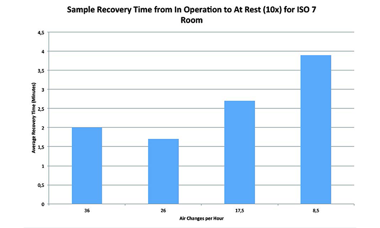
Experimental data from various ISO 7 and ISO 8 has shown that while air change rates have an impact on the ability of a system to recover particles from the room, the benefits of increasing the air changes can be limited, and sometimes provide no additional benefit.
Figure 3, “Sample recovery time from in operation to at rest for EU Grade C/ISO 7 room,” shows that the recovery time actually improved when the airflow was reduced to below 30 ACH. This is believed to be due to a “sweet point” in the room’s air distribution patterns at this airflow. A room with a poor recovery time may not be a good candidate for air change reduction unless changes can be made to improve the effectiveness of the ventilation.
Recovery testing measures the system’s ability to recover airborne contamination from suspension, and is measured in minutes to reduce airborne particles from the in-operation to at-rest specification.
Classified rooms also have to meet defined limits for microbiological contamination. The HVAC system and room air changes do not directly control microbiological contamination, but have an indirect effect due to the control of total airborne particulates. It is possible, therefore, that a reduction in room air change rate could cause microbiological contamination to increase. In this case, the room ventilation (air change) was doing what it was supposed to do by diluting and removing airborne particles. If this increase in particles is noticeable, then it is quite possible that the higher air changes were, in effect, masking the real problem by dilution and removal of airborne particles. This situation may require restoration of the higher air change rate until the root cause of the microbiological contamination is identified and mitigated. If the increased micro “counts” measured after air change reduction are well below the actual quality/regulatory limits, a review might indicate that the new level is acceptable.
- 1International Conference on Harmonisation of Technical Requirements for Registration of Pharmaceuticals for Human Use. “Quality Risk Management: Q9.” 9 November 2005. http://www.ich.org/fileadmin/Public_Web_Site/ICH_Products/Guidelines/Quality/Q9/Step4/Q9_Guideline.pdf
- 3European Commission. Enterprise and Industry Directorate-General. 1: “Manufacture of Sterile Medicinal Products” (corrected version). 25 November 2008. http://ec.europa.eu/health//sites/health/files/files/eudralex/vol-4/2008_11_25_gmp-an1_en.pdf
- 2US Food and Drug Administration. Guidance for Industry. “Sterile Drug Products Produced by Aseptic Processing—Current Good Manufacturing Practice.” September 2004. http://www.fda.gov/downloads/Drugs/.../Guidances/ucm070342.pdf
Technical and regulatory considerations for rooms without a formal cleanroom classification: e.g., oral dosage, most active pharmaceutical ingredient manufacturing (API)
Individual manufacturing firms may have their own names or internal classifications for such areas (e.g., pharmaceutical, controlled not classified).
Rooms for the manufacture of nonsterile products are usually not required by regulation to have formal cleanroom classifications with defined airborne particle limits for US FDA and European Medicines Agency (EMA) regulated markets. Some other markets may have particle limit expectations (formal or informal).
For these rooms, there is no US FDA or EMA requirement for a minimum room air change rate. Some countries in other markets do have minimum air change requirements (often 10 changes per hour).
The air changes in nonclassified rooms do need to dilute airborne particles as they do in a classified room, but meeting occupational hygiene requirements to ensure a safe environment for people in the room often drives the room’s air change rate more than quality concerns.
API manufacturing areas (traditional small molecule) use many chemicals and it is common for rooms to be rated hazardous due to the presence of potentially flammable vapors. The use of gases, such as nitrogen, that, if released, can displace the oxygen in a room is also common. These rooms can be candidates for air change reduction after evaluation of environmental health and safety considerations, such as whether reducing the air change rate would change the room to a higher hazard rating, increase operator exposure to hazardous substances, create the potential for oxygen deprivation, etc.
Laboratories are often designed to a minimum air change rate. Like API areas, for most laboratories, the concerns are greater for EH&S issues than quality. A lab’s air change rate is often based on the assumption that fumes and vapors need to be diluted, either due to normal operations or as the result of a spill. For many labs, however, operations involving chemicals take place inside of fume hoods and not on the open bench-top and it is common to require that all lab occupants immediately exit the room in the case of a spill or similar event to minimize their exposure.
ANSI/AIHA Standard Z-9.5-2012 for Laboratory Ventilation states that “Numerous studies make it clear that the airflow rate is just one factor affecting contaminant levels in a room. Frequently, other factors have been shown to make a bigger difference than some changes in the airflow rate.” 5 Evaluation of laboratories by a team including engineering and EH&S representatives with a good knowledge of the lab operations and substances used will indicate if the lab is a good candidate for reduction of air changes. This is only applicable in labs where the firm’s requirements for a minimum air change rate are the determining factor in setting the air change rate.
Airlocks (both for classified and nonclassified applications)
Many airlocks are also gowning areas, which mean they have high intermittent internal particle generation. They also are transition spaces and, as such, need a short recovery time. Because of this, airlocks are often designed with a higher air change rate than the rooms they connect. Many airlocks are small and the financial savings from reducing air changes may also be small, making the change financially unattractive. Just like other spaces, however, if the airlock is comfortably within airborne particle limits and microbiological limits (where these apply), and has a good recovery time, there is potential for reducing the air changes.
Equipment considerations
Reducing the room air change rate will have an effect on the HVAC system’s components, most notably fans and airflow control devices.
Today, many fans are controlled by a variable speed drive (e.g., VFD) making capacity reduction simple. Even so, there is a limit to how far you can reduce a fan’s flow and still have it operate properly. If the fan is belt-driven and the flow reduction is significant, it may sometimes be advantageous to reduce the fan speed by changing the drive sheaves and belts, even when there is a VFD. In those cases where the fan is not able to operate properly at the reduced flow rate (often because it was oversized to begin with), the fan will limit the amount of the air change reduction, unless of course it is financially attractive to install a smaller fan or modify the existing fan.
One of the desirable effects of air change reduction is a significant reduction in fan power draw. This, of course, means the electric motor driving the fan will be operating significantly below its rated output. In general, retaining the original motor is fine, but sometimes it is advantageous to install a smaller motor if it will be operating so far below its rated output that its efficiency is significantly reduced. Operating a motor in the air stream at a poor efficiency causes additional losses through shedding the additional heat into the air stream. Reduction in this additional heat load will reduce cooling requirements on the system and subsequent electrical energy consumption.
Many HVAC systems have airflow measuring instruments installed in main ducts or in air handling units for monitoring or control. The minimum flow rate (velocity) must be considered, and in some cases changes to the measuring device type or reduction of the size of the duct it is installed in might be needed.
Reducing a room’s air changes involves reducing airflow rates by adjusting dampers. Adjusting manual dampers is often successful as these can be closed almost to shutoff where necessary and fixed in position. Occasionally a manual damper could be so oversized that it will need to be replaced or partially blanked off. The main limitations with dampers are with control dampers, because they can’t operate at the almost fully closed position and still provide proper control. Variable air volume boxes, mechanical constant volume regulators, and similar flow control devices all have upper and lower flow limits. The acceptable flow turndown of these devices will often limit the amount that air changes can be reduced unless it is sufficiently economically attractive to install smaller devices.
HVAC room air supply, return, and exhaust ductwork does not generally limit airflow reduction. Process exhaust flow rates (e.g., dust collection, lab fume hood exhaust) are not normally reduced due to reduction of a room’s minimum air change rate and so this can limit room air change reduction. The amount of outside/fresh air handled by an HVAC system generally remains about the same after an air change reduction as it was before. Although the amount of outside/fresh air may not change, its percentage of the total air handled by the HVAC system will increase because the total airflow will decrease. In climates with cold winters, the winter “mixed-air” temperature needs to be checked to determine if preheating of the air will be needed.
Where HVAC is the dominant load on the facility’s heating and cooling plant (e.g., chillers) and the application of air change reduction and other energy saving approaches is extensive, the ability of the central utilities equipment to operate efficiently at reduced loads should be evaluated.
- 5American Industrial Hygiene Association. ANSI/ASSE Z9.5-2012: American National Standard for Laboratory Ventilation, section 5.3.1, pg. 47.
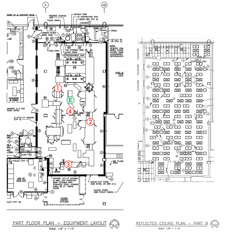
| Challenge | ~4,000,000 parts per minute (at center of room 3 meters from position 1) |
|---|---|
| Position 1 | Filler (line on west side of room) |
| Position 2 | Stopper (line at east side of room) |
| Position 3 | Capper (line at south side of room) |
| Position 4 | Center of room (1 meter from challenge) |
Case Study 1
Company A achieved significant benefits in reduced energy cost through implementation of a data driven approach to optimization of air change rates in GMP manufacturing spaces.
They have accomplished this by using a science-based approach and a standardized process for evaluation, execution, and verification of candidate areas for optimization. Performance data from potential areas is analyzed to evaluate the potential opportunity for optimization of ventilation rates, whilst maintaining the key process parameters for the area within specification. In addition to the operational data analysis, the value of the opportunity is calculated, to ensure the cost of the resources required to execute the change makes business sense.
In one such example, HVAC ventilation rates to an ISO 8/Grade C area were reduced by 25% without impact to key area operating parameters.
Analysis of one-year operating data revealed that significant change could be made without impact to key parameters.
First, the area was evaluated for system and equipment constraints, and the maximum reduction calculated. Then the environmental monitoring data was evaluated and the process capability calculated. With this information, it was confirmed that the area was operating well within the required process requirements.
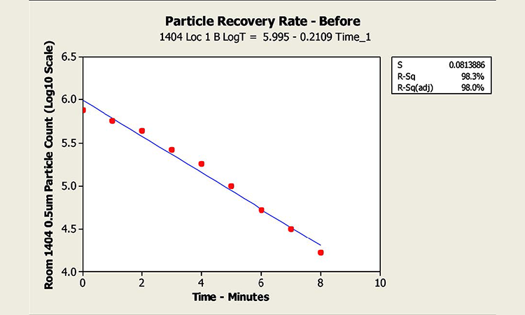
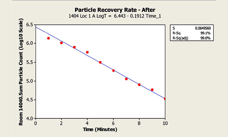
Recertification testing was executed immediately prior to execution of the optimization, and the tests repeated afterward to demonstrate compliance with the required parameters prior to release back to manufacturing. Airborne particle counts and particle recovery testing were included in the recertification.
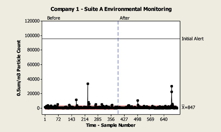
The resulting retest revealed no notable change in the areas operating characteristics. Particle counts (0.5 μm/cubic meter) for the area before and after the test are shown in Figure 4 below. In addition, the results of particle recovery testing showed no significant change, with an average time for a 10x reduction (from in-operation class limit to at-rest) of 4.7 minutes before, and 5.2 minutes after (EudraLex guidance for such an area is the ability to recover from in operation to at rest of 15–20 minutes. See Figure 5 for particle recovery test results.
Energy reductions have been verified in direct fan power, and also in indirect energy such as cooling and reheat requirements. The cost benefits of such reductions have been evaluated at $7–$9 per square meter per ACH per year. This figure is consistent with similar optimization projects across peer facilities.
Case Study 2
Objective
Company B designed an experiment to challenge design practices that utilize high air change rates to maintain particulate levels within classified spaces. The experiment utilized a newly completed sterile diagnostic product filling line, prior to commencing operations. For this reason, a surrogate particulate source was used to simulate the maximum room occupancy. The surrogate emission rate was based on 200,000 0.5μm particles per minute for each occupant at double the expected occupancy.
The intent of the study was to produce sufficient independent data on the performance of subject rooms with regard to both particulate control and recover time at reduced air change rates to inform design and operational standards revision maintained by the quality unit.
Test Method
Multipoint monitoring was undertaken at both return inlets and at area-of-concern (potential product contact) points throughout the subject room(s). The sampling parameters are based on experimental limitations and data-gathering requirements, and are not necessarily aligned with ISO 14644-3:4
- Number of sample locations: 4
- Airflow states: (3) Full flow (45 ACH), half flow (22.5 ACH), minimum flow (15 ACH)
- Particle size sampled: 0.5 μm
- Operational states:
- In operation (until equilibrium particle count is reached)
- Simulated using particulate challenge of 4.0 × 10⁶ particles/minute via Laskin nozzle
- At rest
- De-energize particle generator and observe time to recover to 1% of average ambient particle concentration
- In operation (until equilibrium particle count is reached)
- Sampling time per measurement: 1 cubic foot per minute (with this parameter you can see an increase and decrease of particles—readings shall be at intervals of less than once per minute)
- ISO class limit: 7
- Locations are near the “particle source” and locations equivalent to “filling,” “stoppering,” and “capping”
Test Conditions
Particle counter locations were selected near critical operations and were located without HEPAs directly above them. Particle counters were connected to isokinetic probes by 1.5-meter hoses. The particle generation was located as a single source near the center of the room (see Figure 6 and Table A).
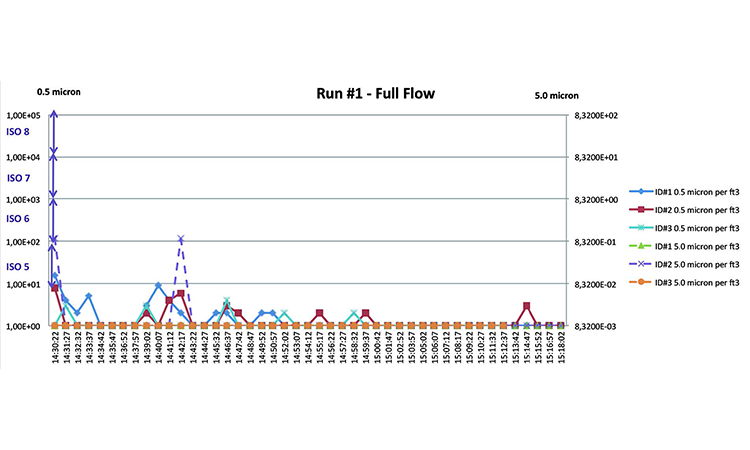
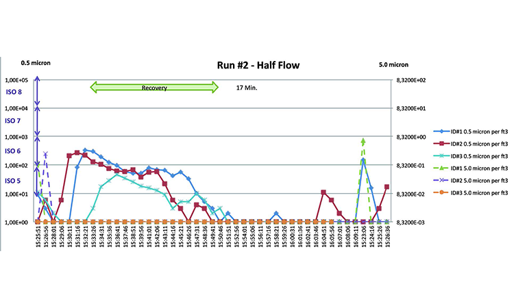
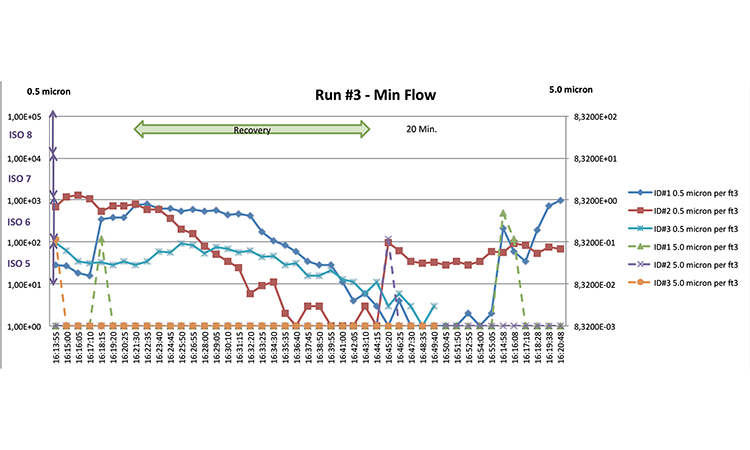
Results
The investigation found that the facility was able to maintain airborne particle count below class limits for class ISO 7 (previously known as Class 10,000) at all flow conditions against a particulate challenge of 4 × 10⁶ particles per minute (Figures 7–9). The facility is easily able to maintain these same conditions at rest using the minimum tested ventilation rate of 15 ACH.
- 4International Organization for Standardization. ISO 14644-3. “Cleanrooms and Associated Controlled Environments—Part 3: Test methods.” 15 December 2005. https://www.iso.org/obp/ui/#iso:std:iso:14644:-3:ed-1:v1:en
Conclusion
The test showed that the facility could reasonably be expected to be requalified successfully at lower airflows during operation and with a night setback scheme, without adverse impact to product quality. The facility now runs at half the original design airflow in operation, and one-third the original when idle!